

 |
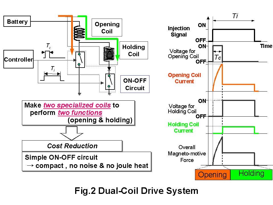
Development of a Battery-Voltage-Driven Fuel Injector for Direct-Injection Gasoline Engines Makoto Yamakado, Hitachi, Ltd., Mechanical Engineering Research Laboratory, Motoyuki Abe, Hitachi, Ltd., Mechanicalü@Engineering Research Laboratory, Yuzo Kadomukai, Hitachi, Ltd., Mechanical Engineering Research Laboratory, Hiromasa Kubo, Hitachi, Ltd., Automotive Products Division and Yasunaga Hamada, Hitachi Car Engineering, Ltd1. Introduction Carbon dioxide (CO2) is the chief culprit in the global-warming phenomenon. Nearly 20% of the CO2 produced by human activity is exhausted from automobiles tailpipes. The Direct-Injection Spark-Ignition (DI-SI) gasoline engine is one of the most promising engine designs for reducing CO2 because of its advantages of reduced fuel consumption and reduced emissions. Hopes run high that the technology will become widespread in the automotive industry. We have developed a battery-voltage-driven fuel injector for DI-SI gasoline engines. The injector is named *VB injector, and it has a dual-coil structure that enables the injector to operate at the battery voltage, thus eliminating the need for either voltage step-up circuitry or current control circuitry. *VB: (Voltage of Battery) The technology is quite effective in reducing the DI-SI system's overall cost, which has been a bottleneck against proliferation of DI-SI gasoline engines for automobiles. 2. Highlights of the Technology The fuel injector for the DI-SI gasoline engine injects fuel directly into the high-pressure cylinders of the engine, so it needs to operate at a high pressure. It also needs to have a fast valve response so that it can inject the precise amount of fuel for each combustion event. The conventional DI-SI gasoline injector is driven by voltage step-up circuitry and current control circuitry. The voltage step-up circuitry boosts the battery voltage to almost 100 volts. After the valve is opened, the current control circuitry maintains the hold current to keep the valve open. The key technologies that let VB injector work without this circuitry are listed below. ć@ Direct battery-voltage-drive technology: The injector has a dual-coil structure with both an opening coil and a holding coil. (Fig.1) The opening coil enhances valve opening, and the holding coil keeps the valve open. Each coil is designed specifically for its purpose, and the injector's design makes it possible to drive it by battery voltage. The driving circuit of the injector is compact and does not generate magnetic noise. This makes the driving circuit easy to install in the engine control unit. (Fig.2) ćAPractical in-automobile application Before the VB injector can be applied to a practical DI-SI gasoline engine, counter-measures against variations in battery voltage and harness resistance are needed. The VB injector ensures reliable fuel injection and optimizes the flow characteristics by controlling the opening-coil energization time in accordance with changes in the battery voltage, harness resistance, and fuel pressure. To be more specific, when the battery voltage drops, harness resistance increases, or fuel pressure increases, the opening-coil energization time should be prolonged. Control of the opening-coil energization time and fuel-injection signal compensation provides the adaptability needed to make the injector suitable for practical use.(Fig.3) 3. Summary The technologies described above drastically reduce the overall cost of the fuel injection system. The production model of the VB injector was introduced to the Japanese market in September 2000 and is currently installed in L4 2.0L, 2.5L, V6 2.5L, 3.0L, and V8 4.5L engines in Japan. This technology has had a profound effect on the proliferation of automobiles with DI-SI gasoline engines and thus has contributed to the prevention of global warming. |
|
|
![]()
|
|
Please feedback us! wwwadmin@jsme.or.jp All Rights Reserved, Copyright (C) 1996, The Japan Society of Mechanical Engineers. |
