 |
Research on Manufacturing Technology for Multi-Layer
Diffractive Optical Element and Applications in Camera Lenses
Masamichi Saito, Production Engineering Research Laboratory, Canon
Inc.
Masaaki Nakabayashi, Production Engineering Research Laboratory,
Canon Inc.
Toru Imanari, Production Engineering Center, Canon
Inc.
Yuichi Miyoshi, Plastic Injection Molds Technology Center, Canon
Inc.
Akihiko Yokoyama, Production Engineering Research Laboratory,
Canon Inc.
1. Abstract
Diffractive optical elements have traditionally been
regarded as unsuitable for use as photographic optical elements due to the
undesirable diffraction flare generated. However, a multi-layer structure,
in which two appropriate diffractive optical layers control the
undesirable diffraction light and thus achieve ideal diffraction
throughout the entire visible light range, has been developed. The result
is the Multi-Layer Diffractive Optical Element, the world's first
diffraction-type optical element applied in photographic lenses.
Such
optical elements were made possible by integrating various technologies,
including a multi-layer structure diffraction grating for controlling the
unwanted diffraction flare, metal mold processing equipment, metal mold
processing technology, molding technology, and other technologies required
to implement the design.
2. Outline of the Technology
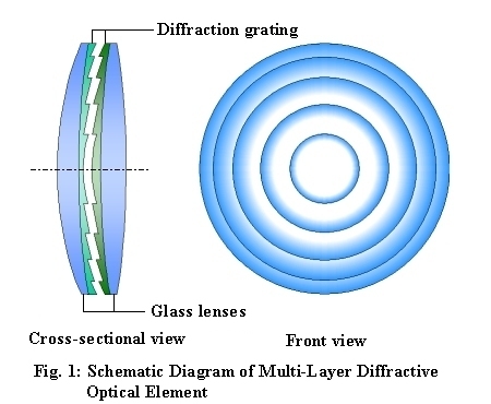
Figure
1 is a schematic diagram of the Multi-Layer Diffractive Optical
Element. On the surface of each glass lens, which is the base material,
there is an element containing a layer of diffraction grating formed by
ultraviolet-curing resin. The grating pitch, grating height, and grating
spacing must precisely match the shape and width specified in the
design.
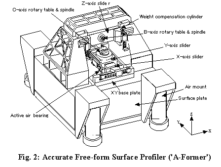
The mold for this diffractive optical element is machined with
a high-precision free-form machine tool as shown in Figure 2. This mold is then used directly as
an optical-element mold, without polishing of the cutting surface. In
consideration of future development of optical molds, this machine tool is
designed to be capable of not only the turning used here but also 5-axis
synchronous machining by an all-axis non-contacting direct drive. The tool
also has a high dynamic stiffness while maintaining a large machining area
(310 x 170 mm) through such methods as FEM analysis. For cost-efficiency,
the machine tool has a speed of 7 mm/s while achieving sufficiently
accurate shape and surface roughness for optical elements.
The shape of
this mold is transfer-molded onto the glass lens using ultraviolet-curing
resin. The curing reaction of the resin is strictly controlled so that
retraction due to hardening is kept to the nanometer level; such strict
management enables the shape of the mold to be compensated by
feedback.
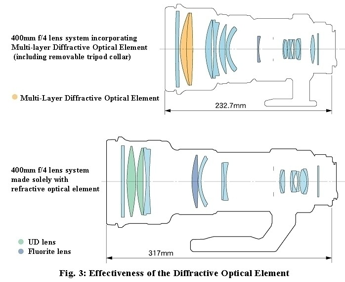
3. Conclusion
As shown in Figure 3,
this Multi-Layer Diffractive Optical Element has made it possible to
create a more compact, lighter EF400mm f/4 lens while maintaining the same
high image quality as in a design consisting only of refraction lenses;
the total length is reduced by about 27% (from 317 mm to 232.7 mm) and the
mass by about 31% (from 3000 g to 2080 g). (The lens with refraction
optical elements is a conceptual design example of our company.)
|


